The blue lines are the outward and inward offset polygons corresponding to the red lines
The topology is preserved as only the geometry changes.
Fernando Cacciola
May, 2003.
According to M. Held [HE91], there is a set-theoretic approach to offsetting
which was initially introduced by Persson [Per78], Harenbrock [Har80], Bruckner[Bru82]
and Diedenhoven [Die84] as a mean to generate tool-paths for countour parallel
pocket machining.
The central idea of all these techniques is to create the offset curve piecewise
and then connect the pieces, remove loops and detect holes in order to arrange
the final result.
Unfortunately, the post-processing of the pieces is so far from trivial that
complex heuristics and ad-hoc procedures are needed.
Furthermore, for most of the published algorithms, specially those for polygon
offseting (instead of parametric curve offseting), counter-examples that break
the algorithms appear more or less frequently in some real world data.
The inherent problem of set-theoretic approaches is the complexity of the reconstruction
of the combinatorial structure of an offset curve. This reconstruction requires
tracking the interaction of different parts of the curve, but this tracking
is difficult because the algorithms basically operates locally.
In consecuence, the topological changes that should ocurr on the true offset
curve are sometimes missed, thus a result is computed but it is locally wrong.
Therefore, alternative methods has been investigated. These methods seek to
overcome the problems due to locality using geometric structures which
contain the complete combinatorial structure needed for the offseting. These
methods are called structural because the offset curves are constructed
directly out of geometric structures naturally suited for such task.
One of this approaches, presented in [HE91], uses a Voronoi Diagram (VD) to
produce rounded or constant-radius offset curves. VD-based offset
curves are strictly parallel to the source curve: each and every point in the
offset curve is exactly at the same distance from the source. Thus, a reflex
vertex in the source curve generates a circular arc in the offset curve (hence
the name rounded)
Another approach has been implicitely described by Aichholzer et. al. in [Ai95].
Their paper presents a novel geometric structure, called a Straight Skeleton
(SK), which is uniquely associated with every simple polygon (possibly multiple
connected) and which corresponds to the trace of the vertices of all the offset
polygons that can be constructed on the inside. The offset curves traced by
a Straight Skeleton are polygons, which means that reflex vertices do not generate
circular arcs as in the case of VD-based offseting. Therefore, such offseting
geometry is usually called mittered, and each offset polygon edge is
not at the same distance to the source polygon edges but to the lines
supporting such edges.
This document explores some of the details of the straight skeleton approach
to polygon offseting; details which in turn expose the inherent limitations
of set-theoretic approaches to offsetting.
Consider a Jordan Curve 'P' (such as a polygon) and imagine that every
point on the curve is set on fire so that the curve consumes itself until the
different fire fronts meet. The trace of the ignited curve, which can be seen
as a normal inward shrinking of the curve, is called a Grassfire Transform,
and is an instance of the constant-speed Front Propagation problem
(see [Ma] for a general description of the front propagation model).
Front propagation problems, and in particular, the constant-speed case, has
been investigated mostly in the fields of Image Processing.
Grassfire-like transformations are obtained directly from an image using the
Morphological Operations known as Erosion or Dilatation;
which are used to shrink or expand the boundary of an image object. Additionally,
exaustive boundary shrinking (that is, until the fronts meet) can be performed
and the process is known as Skeletonization. In particular, the Skeleton
of an image feature can be obtained by means of the Medial Axis Transform
(MAT).
All these standard Image Processing operations are described in most image processing
textbook, and many internet sites contains online tutorials..
C++ code and some references for some of these image-based operations can be
found on: www.magicsoftware.com
An offset curve can be viewed as a snapshot of the contour evolution
under the grassfire transform at a given instant: when the transformed
countour is at given offset distance from the original. Thus, to understand
the kind of combinatorial problems that arise on offseting, it is useful to
analyze how curve pieces (edges) evolve during this transform. Whatever the
algorithm to be used, it has to know how to handle the topological changes
of the curve pieces during the front propagation.
In the sequel, consider the case of a polygon: a jordan curve made of
a sequence of connected edges which are straight line segments, joined
by common points called vertices.
In the case of the so-called mittered-offset (as traced by a Straight
Skeleton), the edges move at constant speed along those lines which bisect two
edges, that is, along angular bisectors. Edges expand and/or contract
as they move, but they always remain parallel to the source edges (that
is, any mittered-offset polygon only contains edges which are parallel to some
source polygon edge).
If during the front propagation, edges only expand and/or contract (without
reaching length zero), the topology of the polygon is preserved. That
is, the offset polygon has the exact same connected set of edges than the source.
Only the geometry changes (edges have different lengths now).
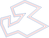
Figure 1:
The blue lines are the outward and inward offset polygons corresponding to the
red lines
The topology is preserved as only the geometry changes.
However, two kind of events might ocurr which do change the topology
of the offset polygon; that is, after such events, the offset polygons hsa a
different set of connected edges..
An edge might contract until it vanishes, even if it started expanding. This
is called an edge event.
After an edge event, the edge no longer appears in the offset polygon.
Figure 2:
This figure shows a sequence of inward offsets (black) of a source convex polygon
(red).
The propagation of some edges are highligthed to show edge events.
The edge fronts drawn in green, cyan, blue and yellow collapse at different
instants, that is, at different distances from the lines supporting the source
edges.
Colser edges collapse first.
After an edge collapses it is no longer contained in the offset polygon.
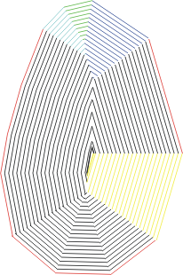
Right after the very last offset polygon, at the maximum allowed offset distance,
all remaining edges collapses. This corresponds the a simultaneous closing
edge event. The yellow edge is one of the edges that collpases at the closing
event.
Edge events are the result of a coallision between two disjoint edge fronts
which oclude the collapsing edge. For example, the green edge collapses after
the coallision of the cyan and blue edges.
Thinking of the polygon offseting as a front propagation, events occurr at
diferent instants, but thinking geometrically, events, which are topological
changes affecting edges, ocurr at a given offset distance from the line
supporting the edge. Determining the instant of an event amounts to calculating
the distance from the supporting lines of the edges involved where the event
ocurrs. Since an edge event is the result of the coallision of two disjoints
edges that oclude a third edge; and since edges move along bisectors, edge events
are the result of bisector intersections, and the corresponding instant is given
by the distance from the intersection point to the lines supporting the two
colliding and the collapsing edges (it should be the same for the three egdes).
An initial edge event is the result of the coallision of its inmediately
adjacent edges and can be computed by intersecting the left and right bisectors
of a single edge. For example, the collapsing of the green edge (in Figure 2)
is an initial edge event.
Because each event changes the topology, only initial edge events can be determined
a priori with trivial local procedures. The reason is that a given edge
which would collide at a given instant might have collapsed before that. Therefore,
it is far more efficient to precompute initial edge events and then detect further
edge events one at a time in the order of ocurrence, so that new edge events
are searched from the updated topology.
In a convex polygon only edge events ocurr. Therefore, convex polygon offseting
can be computed incrementally by determining the first edge event (the closer
to the source supporting line), then creating the new offset polygon without
this edge, and proceeding again detecting the next edge event from the updated
polygon. If a given next edge event ocurrs after the requested distance, the
final result is constructed by a simple offset of the last updated polygon (but
this time without the topolgy reconfiguration).
If the source polygon is non-convex, reflex vertices (with interior angles >
PI) induce a propagation of the consecutive edges at the reflex vertex
which might collide with another edge front splitting such oposite edge.
This is called an split event, and it changes the topology because after
the event the split edge branches two disjoint offset polygons which propagate
independently.
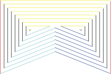
Figure 3:
This figure shows a sample offseting of a non-convex polygon.
The cyan and blue edges move toghether and eventually collide with the yellow
edge.
After the coallision, there are two disjoint polygons propagating.
The split edge (yellow) is contained (partially) in the subsequent offset polygons
after the event.
Unfortunately, split events are non-local. The reflex front (the two consecutive edges moving along a bisector emerging from a reflex vertex), might collide and split almost any other edge in the polygon, even those edges which initially do not cross the line describing the trayectory of the reflex front (the reflex bisector). The reason for this is that edges might expand while they propagate, so at a given distance, an expanded edge might get in the way of a reflex front and produce a split event.
The instant of a split event is also determined by the distance from the point
where the oposite edge is split to the lines supporting the split edge and the
two edges of the reflex front (this distance must be the same for the three
edges, as in the case of the edge event).
If for a given non-convex polygon, the instant for the first split event is
known, and such instant comes after the required offset distance for
the requested offset polygon, the offseting may proceed incrementally as if
the polygon were convex, that is, by detecting each edge event at a time and
updating the topology for the detection of the next edge event.
Split events ocurr only from the edges at a reflex vertex. For each reflex
vertex in the source polygon, it is possible to compute its corresponding split
event by performing an exaustive search against all the other edges. For each
candidate oposite edge, a candidate split point is computed and the closer split
point determines the split event for the reflex front emerging from the reflex.vertex.
The split point search must be performed against all other edges (and considering
their supporting lines) because edges which are not initially visible from the
reflex vertex might be visible later on becasue of possible edge expansions.
It can be shown that if a reflex vertex produces a split, non of the two subsequent offset polygons contain the offseted projection of such reflex vertex (that is, the two new polygons have convex vertices at the split point). Therefore, all possible split events can be precomputed before any of the offset polygons are constructed (using the exaustive search mentioned above).
However, since events change the topology, a given precomputed split event
might never actually ocurr. This is because the candidate oposite edge might
not be actually in the way of the reflex wavefront at the precomputed instant,
both because of prior edge or split events.
Additionally, precomputed edge events (such as inital edge events) might never
ocurr if any split event ocurred before.
As explained in the previous section, the topologial changes that ocurr during
the front propagation, which must be reflected in the offset polygon at any
given distance, are the result of the coallision of disjoint source edges. This
implies that the construction of an offset curve is esentially a combinatorial
problem.
Traditional divide-and-conquer or incremental algorithms are bounded to fail
because they do not explicitely detect all posible interactions.
For example, two edge fronts from completely unrelated parts of the source polygon
might collide producing an edge event thus swepping out a large portion of the
source. Incremental algorithms must be able to track the entire sequence of
edge events in order to determine the topology of the result. Algorithms
resorting only to geometric information (such as intersections between
individual offset edges) might include in the result an edge which shouldn't
be included, thus outputing a polygon which is defective.
The situation is even more complex when reflex vertices are involved since they might split an edge resulting in multiple offset curves. Furhermore, different reflex vertices might produce multiple splits of the same edge. Again, the correct topology is very hard to construct with geometric information only.
If the input polygon is convex and reflex vertices introduce split events which ocurr before the desired offset distance, almost any non-combinatorial algorithm will fail. Only the algorithm that contructs a Straight Skeleton is completely suited for mittered offseting because the algorithm is specifically tracking all front interactions and therefore implicitely computing a continuous offseting, outputing the traces of the moving vertices during the propagation.
It is possible to reduce (perhaps significantly) the combinatorial complexity of a given input by rounding reflex vertices: the sharper the vertex the deeper the possible coallision with an oposite front. Smooth vertices reduces that chances of significant topological changes which might be missed by set-theoretic algorthims.
Image based offseting is possible. It's running time is a factor of the source
polygon size (perimeter and area) and the offset distance, but they always produce
correct results.
Although trivial to implement (see the references about morphological operations
given at the beggining) they produce only rounded offseting.
Only the image-based offseting is truly reliable.
Offseting based on the Straight Skeleton is only unreliable down to the numerical
issues which can arise during the SK computation, but once the SK is constructed,
the building of the offset polygon is pretty robust (there are very corner-case
numerical issues invoved).
As explained, non-combinatorial algorithms are unreliable in general unless
augmented with some of the techniques used by the SK (but hybrid approaches
have not been reported as far as I know).
Because of its non-ombinatorial nature, traditional analitic set-theoretic algorithms are the fastest.
SK-based offseting requires some time to create the SK, but the algorithm presented
by Felkel [Fe98] is pretty fast.
However, because of numerical issues, a real implementation must be able to
deal with imprecise calculations.
One possibility is to use only fast floating point arithmetic but verify the
result and in case of failure try again a number of times after a very small
geometric perturbation. Therefore, the effective running time might be significant
for some worst-case data.
Additionally, because of numerical issues, the SK construction might fail altogheter
unless exact arithmetic is used, which currently runs rather slow for this sort
of problems.
However, the author have succeeded to implement a fast SK computation algorithm
which has been proven to perform sufficientlty fast with TrueType glyphs.
Notice that any analitical algorithm, specially those performing intersection computations and reconstructing topological information from the intersection points are bounded to problems due to numerical errors, so in this regard the SK algorithm is not particularly more sensible to impresicion than any of the set-theoretic approaches.
Image-based algorithms are free from numerical errors and topological incosistences but are significantly slower than the analitical counerparts. Still, due to its simplicity, they might offer a good solution for certain combinations of input size and required offset distances.
The implementation of the staright skeleton algorithm is not much complex than
the implementation of most other computational geometric algorithms involving
distance and intersection calculations.
The image-based algorithms are rather easy to implement.
[HE91] M. Held. "On the Computational Geometry ofPocket Machining", LNCS500, Springer-Verlag,1991
[Per78] H. Persson. "NC Machining of Arbitrarily Shaped Pockets", CAD, 1978
[Har80] D. Harenbrock. "The Connection of CAD and CAM by Means of the Program Package PROREN1/NC". 1980
[Bru82] L.K. Bruckner. "Geometric Algorithms for 21/2D Roughing Process of Scluptured Surfaces" 1982
[Die84] H. Diedenhoven. "Application of CAD Techniques for the Generation of Coallision-free Tool-Paths for NC Machines with Five Axes"
[Ai95] O. Aichholzer. et. al. "A Novel Type of Skeleton for Polygons", 1995.
[Ma] R. Malladi. et. al. "Shape Modeling with Front Propagation: A Level Set Approach"
[Fe98] P. Felke. et. al. "Straight Skeleton Implementation"